Building Your Own SoC#

This tutorial will walk you through the process of building an ASIC containing one PicoRV32 RISC-V CPU core and 2 kilobytes of SRAM, on an open-source 130nm Skywater process node, with SiliconCompiler’s remote workflow:

../../_images/picorv32_ram_screenshot.png

We will walk through the process of downloading the design files and writing a build script, but for your reference, you can find complete example designs which reflect the contents of this tutorial in the public SiliconCompiler repository. The first part of the tutorial will cover building the CPU core without RAM, and the second part will describe how to add an SRAM block.

See the Installation section for information on how to install SiliconCompiler, and the Remote Processing section for instructions on setting up the remote workflow.

Download PicoRV32 Verilog Code#

The heart of any digital design is its HDL code, typically written in a language such as Verilog or VHDL. High-level synthesis languages are gaining in popularity, but most of them still output their final design sources in a traditional HDL such as Verilog.

PicoRV32 is an open-source implementation of a small RISC-V CPU core, the sort you might find in a low-power microcontroller. Its source code, license, and various tooling can be found in its GitHub repository.

Build the PicoRV32 Core using SiliconCompiler#

Before we add the complexity of a RAM macro block, let’s build the core design using the open-source Skywater 130 PDK. Copy the following build script into the same directory which you copied picorv32.v into:

<project_dir>/picorv32.py#
#!/usr/bin/env python3
import siliconcompiler


def rtl2gds(target="skywater130_demo"):
    '''RTL2GDS flow'''

    # CREATE OBJECT
    chip = siliconcompiler.Chip('picorv32')

    # SETUP
    chip.load_target(target)

    chip.register_package_source(name='picorv32',
                                 path='git+https://github.com/YosysHQ/picorv32.git',
                                 ref='c0acaebf0d50afc6e4d15ea9973b60f5f4d03c42')

    chip.input('picorv32.v', package='picorv32')

    chip.set('option', 'relax', True)
    chip.set('option', 'quiet', True)
    chip.set('option', 'remote', False)

    chip.clock('clk', period=25)

    # RUN
    chip.run()

    # ANALYZE
    chip.summary()

    return chip


if __name__ == '__main__':
    rtl2gds()

Note in the code snippet above that remote is set to False. If this is set to True, this means it is set up for Remote processing, and if you run this example as a Python script, it should take approximately 20 minutes to run if the servers are not too busy. 
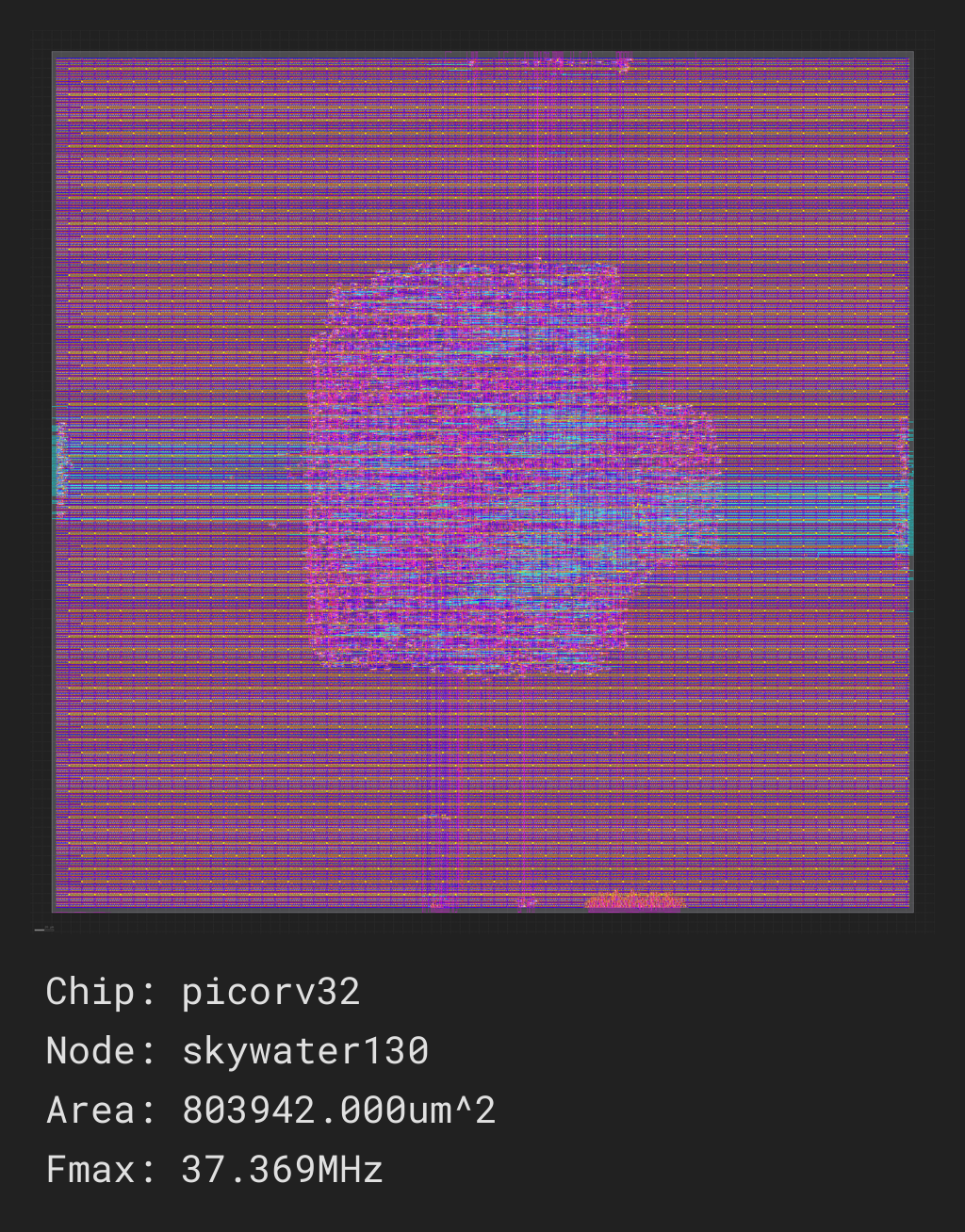
We have not added a RAM macro yet, but this script will build the CPU core with I/O signals placed pseudo-randomly around the edges of the die area. Once the job finishes, you should receive a screenshot of your final design, and a report containing metrics related to the build in build/picorv32/job0/report.html. SiliconCompiler will try to open the file after the job completes, but it may not be able to do so if you are running in a headless environment.

../../_images/picorv32_screenshot.png

For the full GDS-II results and intermediate build artifacts, you can run the build locally. See the Local Run section for more information.

Adding an SRAM block#

A CPU core is not very useful without any memory. Indeed, a real system-on-chip would need quite a few supporting IP blocks to be useful in the real world. At the very least, you would want a SPI interface for communicating with external non-volatile memory, a UART to get data in and out of the core, a debugging interface, and a small on-die cache.

In this tutorial, we’ll take the first step by adding a small (2 kilobyte) SRAM block and wiring it to the CPU’s memory interface. This will teach you how to import and place a hard IP block in your design.

The open-source Skywater130 PDK does not currently include foundry-published memory macros. Instead, they have a set of OpenRAM configurations which are blessed by the maintainers. You can use those configurations to generate RAM macros from scratch if you are willing to install the OpenRAM utility, or you can download pre-built files.

We will use the sky130_sram_2kbyte_1rw1r_32x512_8 block in this example.

Create a Python script called sky130_sram_2k.py to describe the RAM macro in a format which can be imported by SiliconCompiler:

<project_dir>/sky130_sram_2k.py#
import os
import siliconcompiler


def setup(chip):
    # Core values.
    design = 'sky130_sram_2k'
    stackup = chip.get('option', 'stackup')

    # Create library Chip object.
    lib = siliconcompiler.Library(chip, design)
    lib.register_package_source('vlsida',
                                'git+https://github.com/VLSIDA/sky130_sram_macros',
                                'c2333394e0b0b9d9d71185678a8d8087715d5e3b')
    lib.set('output', stackup, 'gds',
            'sky130_sram_2kbyte_1rw1r_32x512_8/sky130_sram_2kbyte_1rw1r_32x512_8.gds',
            package='vlsida')
    lib.set('output', stackup, 'lef',
            'sky130_sram_2kbyte_1rw1r_32x512_8/sky130_sram_2kbyte_1rw1r_32x512_8.lef',
            package='vlsida')

    rootdir = os.path.dirname(__file__)
    lib.set('output', 'blackbox', 'verilog', os.path.join(rootdir, "sky130_sram_2k.bb.v"))
    # Ensure this file gets uploaded to remote
    lib.set('output', 'blackbox', 'verilog', True, field='copy')

    return lib

You will also need a “blackbox” Verilog file to assure the synthesis tools that the RAM module exists: you can call this file sky130_sram_2k.bb.v. You don’t need a full hardware description of the RAM block to generate an ASIC design, but the open-source workflow needs some basic information about the module:

<project_dir>/sky130_sram_2k.bb.v#
(* blackbox *)
module sky130_sram_2kbyte_1rw1r_32x512_8 (
`ifdef USE_POWER_PINS
    vccd1,
    vssd1,
`endif
    // Port 0: RW
    input clk0,
    input csb0,
    input web0,
    input [3:0] wmask0,
    input [8:0] addr0,
    input [31:0] din0,
    output reg [31:0] dout0,
    // Port 1: R
    input clk1,
    input csb1,
    input [8:0] addr1,
    output reg [31:0] dout1
);
endmodule

Next, you need to create a top-level Verilog module containing one picorv32 CPU core, one sky130_sram_2k memory, and signal wiring to connect their I/O ports together. Note that for the sake of brevity, this module does not include some optional parameters and signals:

<project_dir>/picorv32_top.v#
`timescale 1 ns / 1 ps

module picorv32_top #(
    parameter [0:0] ENABLE_COUNTERS = 1,
    parameter [0:0] ENABLE_COUNTERS64 = 1,
    parameter [0:0] ENABLE_REGS_16_31 = 1,
    parameter [0:0] ENABLE_REGS_DUALPORT = 1,
    parameter [0:0] LATCHED_MEM_RDATA = 0,
    parameter [0:0] TWO_STAGE_SHIFT = 1,
    parameter [0:0] BARREL_SHIFTER = 0,
    parameter [0:0] TWO_CYCLE_COMPARE = 0,
    parameter [0:0] TWO_CYCLE_ALU = 0,
    parameter [0:0] COMPRESSED_ISA = 0,
    parameter [0:0] CATCH_MISALIGN = 1,
    parameter [0:0] CATCH_ILLINSN = 1,
    parameter [0:0] ENABLE_PCPI = 0,
    parameter [0:0] ENABLE_MUL = 0,
    parameter [0:0] ENABLE_FAST_MUL = 0,
    parameter [0:0] ENABLE_DIV = 0,
    parameter [0:0] ENABLE_IRQ = 0,
    parameter [0:0] ENABLE_IRQ_QREGS = 1,
    parameter [0:0] ENABLE_IRQ_TIMER = 1,
    parameter [0:0] ENABLE_TRACE = 0,
    parameter [0:0] REGS_INIT_ZERO = 0,
    parameter [31:0] MASKED_IRQ = 32'h0000_0000,
    parameter [31:0] LATCHED_IRQ = 32'hffff_ffff,
    parameter [31:0] PROGADDR_RESET = 32'h0000_0000,
    parameter [31:0] PROGADDR_IRQ = 32'h0000_0010,
    parameter [31:0] STACKADDR = 32'hffff_ffff
) (
    input clk,
    resetn,
    output reg trap,

    // Look-Ahead Interface
    output            mem_la_read,
    output            mem_la_write,
    output     [31:0] mem_la_addr,
    output reg [31:0] mem_la_wdata,
    output reg [ 3:0] mem_la_wstrb,

    // Pico Co-Processor Interface (PCPI)
    output reg        pcpi_valid,
    output reg [31:0] pcpi_insn,
    output     [31:0] pcpi_rs1,
    output     [31:0] pcpi_rs2,
    input             pcpi_wr,
    input      [31:0] pcpi_rd,
    input             pcpi_wait,
    input             pcpi_ready,

    // IRQ Interface
    input      [31:0] irq,
    output reg [31:0] eoi,

`ifdef RISCV_FORMAL
    output reg        rvfi_valid,
    output reg [63:0] rvfi_order,
    output reg [31:0] rvfi_insn,
    output reg        rvfi_trap,
    output reg        rvfi_halt,
    output reg        rvfi_intr,
    output reg [ 1:0] rvfi_mode,
    output reg [ 1:0] rvfi_ixl,
    output reg [ 4:0] rvfi_rs1_addr,
    output reg [ 4:0] rvfi_rs2_addr,
    output reg [31:0] rvfi_rs1_rdata,
    output reg [31:0] rvfi_rs2_rdata,
    output reg [ 4:0] rvfi_rd_addr,
    output reg [31:0] rvfi_rd_wdata,
    output reg [31:0] rvfi_pc_rdata,
    output reg [31:0] rvfi_pc_wdata,
    output reg [31:0] rvfi_mem_addr,
    output reg [ 3:0] rvfi_mem_rmask,
    output reg [ 3:0] rvfi_mem_wmask,
    output reg [31:0] rvfi_mem_rdata,
    output reg [31:0] rvfi_mem_wdata,

    output reg [63:0] rvfi_csr_mcycle_rmask,
    output reg [63:0] rvfi_csr_mcycle_wmask,
    output reg [63:0] rvfi_csr_mcycle_rdata,
    output reg [63:0] rvfi_csr_mcycle_wdata,

    output reg [63:0] rvfi_csr_minstret_rmask,
    output reg [63:0] rvfi_csr_minstret_wmask,
    output reg [63:0] rvfi_csr_minstret_rdata,
    output reg [63:0] rvfi_csr_minstret_wdata,
`endif

    // Trace Interface
    output reg        trace_valid,
    output reg [35:0] trace_data
);

    // Memory signals.
    reg mem_valid, mem_instr, mem_ready;
    reg [31:0] mem_addr;
    reg [31:0] mem_wdata;
    reg [ 3:0] mem_wstrb;
    reg [31:0] mem_rdata;

    // No 'ready' signal in sky130 SRAM macro; presumably it is single-cycle?
    always @(posedge clk) mem_ready <= mem_valid;

    // (Signals have the same name as the picorv32 module: use '.*')
    picorv32 rv32_soc (.*);

    // SRAM with always-active chip select and write control bits.
    sky130_sram_2kbyte_1rw1r_32x512_8 sram (
        .clk0  (clk),
        .csb0  ('b0),
        .web0  (!(mem_wstrb != 0)),
        .wmask0(mem_wstrb),
        .addr0 (mem_addr),
        .din0  (mem_wdata),
        .dout0 (mem_rdata),
        .clk1  (clk),
        .csb1  ('b1),
        .addr1 ('b0),
        .dout1 ()
    );
endmodule

Finally, your core build script will need to be updated to import the new SRAM Library, and specify some extra parameters such as die size and macro placement:

<project_dir>/picorv32_ram.py#
#!/usr/bin/env python3

import os
import siliconcompiler


def build_top():
    # Core settings.
    design = 'picorv32_top'
    target = 'skywater130_demo'
    die_w = 1000
    die_h = 1000

    # Create Chip object.
    chip = siliconcompiler.Chip(design)

    # Set default Skywater130 PDK / standard cell lib / flow.
    chip.load_target(target)

    # Set design source files.
    chip.register_package_source(name='picorv32',
                                 path='git+https://github.com/YosysHQ/picorv32.git',
                                 ref='c0acaebf0d50afc6e4d15ea9973b60f5f4d03c42')
    chip.input(os.path.join(os.path.dirname(__file__), f"{design}.v"))
    chip.input("picorv32.v", package='picorv32')

    # Optional: Relax linting and/or silence each task's output in the terminal.
    chip.set('option', 'relax', True)
    chip.set('option', 'quiet', True)

    # Set die outline and core area.
    margin = 10
    chip.set('constraint', 'outline', [(0, 0), (die_w, die_h)])
    chip.set('constraint', 'corearea', [(margin, margin),
                                        (die_w - margin, die_h - margin)])

    # Setup SRAM macro library.
    import sky130_sram_2k
    chip.use(sky130_sram_2k)
    chip.add('asic', 'macrolib', 'sky130_sram_2k')

    # SRAM pins are inside the macro boundary; no routing blockage padding is needed.
    chip.set('tool', 'openroad', 'task', 'route', 'var', 'grt_macro_extension', '0')
    # Disable CDL file generation until we can find a CDL file for the SRAM block.
    chip.set('tool', 'openroad', 'task', 'export', 'var', 'write_cdl', 'false')
    # Reduce placement density a bit to ease routing congestion and to speed up the route step.
    chip.set('tool', 'openroad', 'task', 'place', 'var', 'place_density', '0.5')

    # Place macro instance.
    chip.set('constraint', 'component', 'sram', 'placement', (500.0, 250.0, 0.0))
    chip.set('constraint', 'component', 'sram', 'rotation', 180)

    # Set clock period, so that we won't need to provide an SDC constraints file.
    chip.clock('clk', period=25)

    # Run the build.
    chip.set('option', 'remote', False)
    chip.set('option', 'quiet', False)

    chip.run()

    # Print results.
    chip.summary()

    return chip


if __name__ == '__main__':
    build_top()

With all of that done, your project directory tree should look something like this:

<rundir>
├── sky130_sram_2k.bb.v
├── sky130_sram_2k.py
├── picorv32.py
├── picorv32_ram.py
└── picorv32_top.v

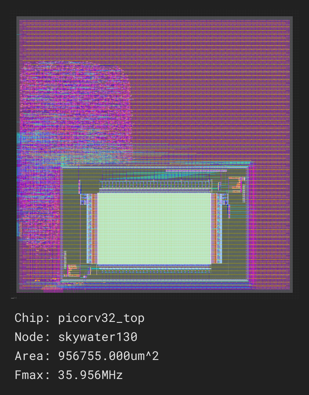
Your picorv32_ram.py build script should take about 20 minutes to run on the cloud servers if they are not too busy, with most of that time spent in the routing task. As with the previous designs, you should see updates on its progress printed every 30 seconds, and you should receive a screenshot once the job is complete and a report in the build directory:

../../_images/picorv32_ram_screenshot.png

Extending your design#

Now that you have a basic understanding of how to assemble modular designs using SiliconCompiler, why not try building a design of your own creation, or adding a custom accelerator to your new CPU core?